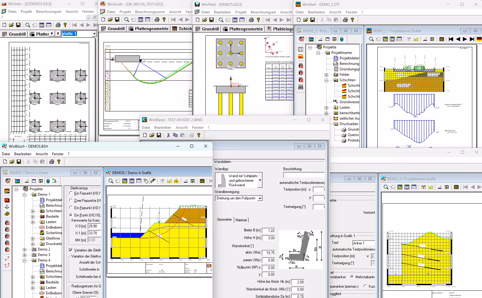
Overview of programs for geostatic analysis:
* WinBösch – Stability of embankments and slopes according to DIN 4084, the new DIN 1054, and EC 7, using circular slip surfaces according to Bishop, fractured slip surfaces according to Janbu and Morgenstern, and block slip surfaces (composite rigid-body mechanism)
* WinNagel – internal and external stability of nailed retaining structures with circular sliding surfaces according to Bishop and with block sliding surfaces (composite rigid-body mechanism) according to DIN 1054 (old) / 1054 (new), EC 7
* WinPfahl – Pile foundations (single piles and pile groups) in accordance with DIN 4014, the new DIN 1054, EC 7, and EA piles
* WinSetz – Settlement and tilt calculation in accordance with DIN 4019 Parts 1 and 2, and the new DIN 1054; accounts for time-dependent settlement (including for vertical drains)
* WinGrubru – Uplift resistance analysis for rectangular and circular isolated foundations as well as strip foundations, and punching shear analysis for layered soils in accordance with DIN 4017 and the new DIN 1054
* WinSteif – Foundation slabs designed using the stiffness modulus method in accordance with DIN 4018, EC 7, and DIN 1054
* WinWand – Earth pressure calculation for rigid retaining walls and abutments (underpinning, angled retaining walls, etc.) in accordance with DIN 4085, the new DIN 1054, and EC 7
* WinBaugr – Calculation and design of excavation walls in accordance with EAB and DIN 4124, the new DIN 1054, and EC 7
The soil mechanics programs allow calculations to be performed in accordance with both the current version of Eurocode 7 (using partial safety factors) and the older DIN standards (using a global safety factor). The safety factors can be determined by the program in accordance with the standard or modified manually.
The output pages can be exported in various formats and further processed (as EMF and DXF graphics, or as HTML files).
You can incorporate your company name and, if available, your company logo into the output forms. These settings can be applied to all other WinGeo programs. For the stamp field, project data (such as construction project, processor, etc.) can be customized and saved as company-specific default settings.

The WinBösch program allows you to determine the stability of slopes and terrain in accordance with DIN 4084, the new DIN 1054, and EC 7 using various types of slip surfaces:
* with circular sliding surfaces according to Bishop (rotational mechanism)
* with broken sliding surfaces according to Janbu and Morgenstern ( composed of circles, polygons, layer boundaries, etc., in any configuration)
* with block-and-slide surfaces (composite rigid-body mechanism).
The interface is structured similarly to Windows Explorer. The input tree simplifies data entry and provides a clear overview of all entries, which are displayed graphically in a separate window. Within the input tree, individual elements or entire projects can be copied and pasted. For each input screen, on-screen help is available within the program by pressing the F1 key.
Input:
* Any number of layers, loads, and components (structures of any geometry, anchors with or without prestressing, geotextiles)
* Groundwater and surface water
* Settings for sliding surfaces: Size, constraint points, search grid / number of variations
* Settings for pore water pressure, earthquakes, and calculation standards
* Settings for printable pages: page size and layout (with options to hide elements), stamp field, page layout, labels, etc.
* Entering coordinates (e.g., for layer boundaries, load points, or sliding circle coordinates) either graphically using the mouse in the output window or via dialog boxes in the project window.
* It is possible to mirror the entire system (layers, structures, anchors, geotextiles, loads, etc.) along the vertical axis so that, for example, the stability of both sides of a dam can be determined.
Evaluation and output:
* Output of all entered data as a graph and report (slope geometry, layers, etc.)
* Stability analysis using the critical (worst-case) sliding surface and all calculated values.

The WinNagel program can be used to determine the stability of nailed retaining walls in accordance with DIN 1054 (old and new versions) and EC 7 . The following calculations can be performed:
* Internal bracing of a boarded-up retaining wall using
- a rotational mechanism (circular sliding line according to Bishop)
- or a translation mechanism (composite rigid-body fracture mechanisms)
- Load distribution for the structural analysis of the wall's individual components (nails, outer shell).
* External security:
- Earthquake resistance of the entire structure
- Slip, tilt, and foundation failure resistance.
The interface is structured similarly to Windows Explorer. The input tree simplifies data entry and provides a clear overview of all entries, which are displayed graphically in a separate window. Within the input tree, individual elements or entire projects can be copied and pasted. For each input screen, on-screen help is available within the program by pressing the F1 key.
Input:
* Any number of layers and loads
* Components: a nail-connected wall (outer shell) and any number of other structures with any geometry
* Any number of nails with associated data: nail thrust forces and length, lateral spacing, vertical spacing, attachment point, etc. / simplified input for all nails (when nails are evenly spaced) or for each nail individually.
* Groundwater and surface water
* Settings for sliding surfaces: Size, constraint points, search grid / number of variations
* Settings for pore water pressure, earthquakes, and calculation standards
* Settings for printable pages: page size and layout (with options to hide elements), stamp field, page layout, labels, etc.
* Entering coordinates (e.g., for layer boundaries, load points, or sliding circle coordinates) either graphically using the mouse in the output window or via dialog boxes in the project window.
Evaluation and output:
* Output of all entered data as a graphic and report (slope geometry, layers, pile arrangement, etc.) as well as the force triangle (for block sliding lines)
* Evidence of external structural stability (for the entire system consisting of a nailed-down floor area and a nailed-to-wall connection serving as a rigid replacement wall) and of internal structural stability (for individual components of the nailed wall: individual nails and the outer skin).

The WinPfahl program is used for the geotechnical design of pile foundations. It performs calculations for:
* Individual piles (drilled piles, driven piles) as well as
* both horizontal and vertical pile systems.
The calculations are performed in accordance with DIN 4014, the new DIN standard, EC 7, and EA Piles.
WinPfahl also allows for the analysis of the settlement behavior of pile foundations. This analysis takes into account the mutual interaction both within a pile plate and between different pile plates.
Input:
* Any number of pile plates (coordinate input for plan and cross-section) with any number of piles:
- Various layouts (automatic layout also available)
- various angles, materials, foot extensions, head restraints
* Any number of layers: per pile, per slab, or interpolated across borehole points
* Loads: forces and moments in all three coordinate directions; for settlement analysis: distribution of loads between the slab and piles
* Select calculation standard
Evaluation and output:
* Compression pile: Verification of the axial bearing capacity for individual piles
* Non-pressure pile: Verification of pile bearing capacity perpendicular to the pile axis for individual piles, taking into account the reduction in subgrade modulus in pile groups.
* Determination of pile forces within the pile grid using Schiel's method.
* Settlement calculation at any point or along any section and across the entire area (isocurves).

The WinSetz program is used for:
* Determination of settlement and skewing
* Settlement caused by embankment loads or slope loads
* Determination of the settlement curve resulting from delayed consolidation in cohesive, water-saturated soils, whereby the installation of vertical drains to accelerate the settlement of consolidation layers can also be calculated.
The calculation methods are based on DIN 4019, Parts 1 and 2, and the new version of DIN 1054.
Input:
* Any number of foundations with any number of layers and inclined, off-center, or vertical loads.
* Water table, vertical drains, demolition criteria
Evaluation and output:
* The settlement location can be interactively selected at any point using the mouse, and the settlement at that point can be calculated. Similarly, the settlement depression can be determined along the X and Y axes at any point.
* Determination of the tilt angle for each load area.
* Display of the voltage curve at any point.
* The settlement diagram can be presented either for a specific time period or as a function of time and degree of consolidation. In addition, vertical drains can be taken into account to accelerate the settlement of consolidation layers.
* Settlement distribution in the subsurface can be represented using a color scale (including grayscale) (2D contour lines).

The WinGrubru program is used to calculate the ultimate strength of rectangular and circular isolated foundations as well as strip foundations, and to perform punching shear analysis for layered soils. The calculation methods are based on DIN 4017 and the new DIN 1054.
Input:
* Slab geometry: For individual footings or strip footings (with slope, depth)
* Terrain, groundwater, strata
* Loads: simplified or calculated individually for each attachment point and slope
* Specification of the load case in accordance with DIN 1054, design standard
* For soil layering beneath the foundation: unit weight, shear parameters, and cohesion for each layer; a maximum of 20 layers is possible.
* Select whether to perform the punching shear analysis.
Evaluation and output:
* Option 1: The safety factor is determined for a given total load. The system indicates whether the load is permissible for the selected load case.
* Option 2: If no total load has been specified, the calculation determines the maximum total load allowed for the selected load case so that the stress remains within acceptable limits.
* For layered soil, you can choose whether to perform the punching shear analysis for the top layer.
* Varying individual geometric data so that safety requirements are just met.
* Floor plan: Geometry of the specified foundation with the applied loads
* Analysis: Graphical representation of the foundation cross-section, including the layers, the equivalent foundation during punching, and the failure mode for each iteration step.
* Report containing the input data and calculation results.

WinSteif is a program for calculating foundation slabs using the stiffness modulus method in accordance with DIN 4018, DIN 1054, and EC 7. It determines the distribution of base pressure, settlements, bending moments, and shear forces of the slab for any layered soil conditions in the plane case, taking into account the influence of adjacent load areas.
The interface is structured similarly to Windows Explorer. The input tree simplifies data entry and provides a clear overview of all entries, which are displayed graphically in a separate window. Within the input tree, individual elements or entire projects can be copied and pasted. For each input screen, on-screen help is available within the program by pressing the F1 key.
Input:
* Foundation slab divided into sections (in groups or individually)
* Any number of layers: one per field or evenly distributed across the entire width
* Any number of loads per cell and adjacent load areas outside the cells
* Pre-load, depth of excavation, groundwater, lateral excavation
* Selection and settings of the calculation standard
* Settings for printable pages: page size and layout (with options to hide elements), stamp field, page layout, labels, etc.
Evaluation and output:
* Output of all entered data as graphics (2 graphics: for floor plan and cross-section) and a report
* Per span: settlement, bearing pressure, shear force, and bending moment, as well as optional subgrade modulus.

The program is designed to calculate earth pressure, hydrostatic pressure, and base pressure acting on rigid retaining walls, abutments, and angle retaining walls in accordance with DIN 4085, DIN 1054, and EC 7, as well as to perform their structural analysis. Calculations can be performed for the following types of walls:
*Walls with a foundation slab and/or a broken back wall
*Walls with 1 to 4 cantilever arms
*Angled retaining wall
*Gabion walls (rectangular containers made of wire mesh or geogrids, filled with stone or gravel).
The interface is structured similarly to Windows Explorer. The input tree simplifies data entry and provides a clear overview of all entries, which are displayed graphically in a separate window. Within the input tree, individual elements or entire projects can be copied and pasted. For each input screen, on-screen help is available within the program by pressing the F1 key.
Input:
* Select the wall type and enter all geometric data as well as the type of wall movement
* Any number of layers, loads, 1 support (loads can be applied both on the active side of the ground and on the wall.)
* Various terrain contour shapes on the active and passive sides (On the active side of the wall, any number of changes in terrain slope and any number of berms are permitted.)
* Groundwater (including flowing groundwater)
* Settings for active and passive earth pressure and for calculations: calculation standard, assumption of soil resistance for various verifications
*Settings for printable pages: page size and layout (elements can be hidden), stamp field, page layout, labels, etc.
Evaluation and output:
* Output of all entered data as a graph and report
* Determination of earth pressure distribution, water pressure, and bottom pressure, internal forces, and the structural system
* Resistance to sliding, overturning, and foundation failure (in the case of a sloped foundation: in addition to the resistance to sliding provided by the inclined foundation joint, there is also resistance to sliding provided by the substitute shear joint according to Spang).

The program is used to calculate earth pressure and internal forces for excavation walls in accordance with DIN 4124, EAB, and EC 7, as well as to design all wall components. Calculations can be performed for the following types of walls:
* Sheet pile walls (various pre-installed profiles and custom input)
* Beam-and-wall structures (various materials used for infill between the beams, such as compacted soil, concrete, wood, and steel)
* Drilled pile walls (various pile configurations: overlapping, tangential, unlined walls, or walls with intermediate arches)
* Diaphragm walls in the solid state (an add-on module for the liquid state will be available shortly).
The interface is structured similarly to Windows Explorer. The input tree simplifies data entry and provides a clear overview of all entries, which are displayed graphically in a separate window. Within the input tree, individual elements or entire projects can be copied and pasted. For each input screen, on-screen help is available within the program by pressing the F1 key.
Input:
* Select the wall type and enter all geometric data and wall elements
* Any number of layers, loads, supports (anchors and stiffeners), and settlement at the support points (loads can be applied both on the active soil side and on the wall.)
* Various terrain contour shapes on the active and passive sides (On the active side of the wall, any number of changes in terrain slope and any number of berms are permitted.)
* Groundwater (including flowing groundwater)
* Settings for active and passive earth pressure (type of redistribution / proportion of static pressure, types of slip surfaces)
* Calculation settings: Embedment depth / wall restraint level, calculation standard
* Settings for printable pages: page size and layout (with options to hide elements), stamp field, page layout, labels, etc.
Evaluation and output:
* Output of all entered data as a graph and report
* Determination of earth pressure distribution, water pressure, internal forces, and the structural system
* Wall dimensions:
- Documentation of the profiles, determination of the reinforcement, determination of the required cross-sectional values, etc.
* and all individual parts:
- Braces, anchors (design verification for grouted elements and steel tension members, depth of sliding joint)
- Infill (for sheet pile walls and bored pile walls with infill)
* As well as the required safety certifications (balance certificates).


